A canal can look like one continuous strip of water while its route climbs through the landscape. The C&O Canal’s lift locks made that climb in steps. A boat did not sail up a watery slope inside each chamber: the water supporting it changed height. Following one upward passage makes the arrangement easier to understand. This explanation uses the National Park Service’s published accounts and an original schematic, rather than observations from a visit.
Begin with two reaches at different heights
The National Park Service describes lift locks as the vertical steps between flat canal levels. Each chamber has a set of gates at either end. In our upward example, one end connects to the lower reach and the other to the higher reach. Those outside water levels are drawn as fixed references so the chamber’s changing level remains easy to see.
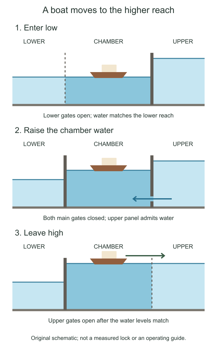
The difference is important when looking at the waterline beside a wall. The boat floats on the chamber water, so raising that water also raises the floating boat. A lock does not need to tilt the boat or pull it up an inclined track to complete this movement. The original diagram leaves out the towpath, masonry details and surrounding landscape to keep this one relationship visible.
First, the boat enters at the lower level
For the first stage, the chamber water matches the lower reach. The lower-end gates are open and the higher-end gates hold back the water above. The boat enters the chamber from the lower side. The NPS account describes ropes used to guide the boat and keep it from striking the walls.
Once the boat is inside, the lower gates close. Both ends now separate the chamber from the neighboring reaches. Closing the entrance is a change in the chamber’s boundary; it does not by itself raise the water. That requires another opening with a different job. Keeping those two jobs distinct helps explain why simply drawing two large doors is not enough to show how the lock works.
Then, water enters through the smaller panels
The NPS description identifies small panels at the bottom of the gates, operated with a lock key. Its shorter account calls these openings wickets. For the upward passage, opening the panels at the higher end allows water into the enclosed chamber. The water level rises, carrying the floating boat with it.
The second stage of the drawing therefore keeps both main gate sets closed while showing water entering from the higher side. The boat has moved upward relative to the chamber wall, although it remains afloat at the water surface. The illustration is a teaching model, not a measured drawing of a named lock or an operating guide. Its proportions and intermediate waterline are chosen to make the change legible.
Notice what has remained unchanged in the picture: the two outside reaches still sit at different heights. The lock has brought a small connecting chamber toward the upper level. It has not flattened the whole canal into a single continuous height.
At equal levels, the upper exit opens
When the chamber water reaches the higher level, the upper gates can be opened and the boat can leave. The third stage shows that match: the chamber and upper reach share a waterline, while the lower reach stays below. The boat continues into the next flat section of canal.
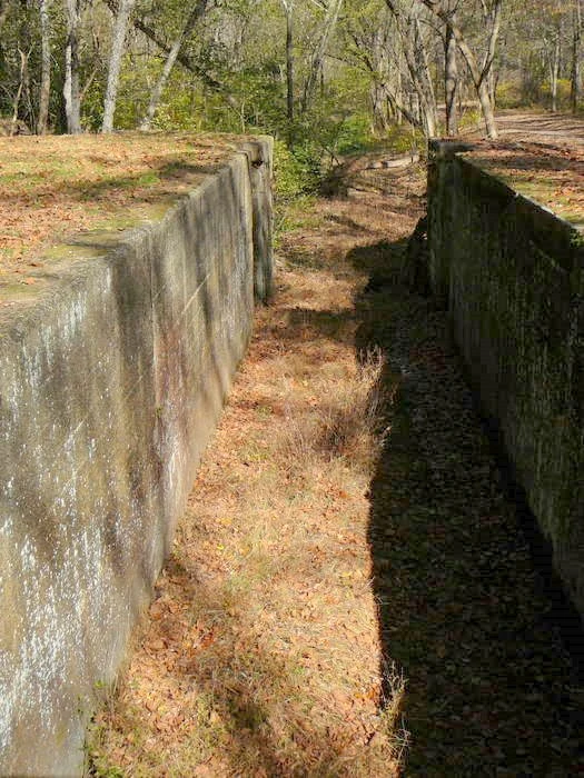
The sequence also explains why a view of an open gate captures only one state. A photograph might show the entrance, the exit or an empty chamber between passages. Without knowing which water levels match, the open doorway alone does not reveal whether a boat is arriving from below or leaving above. Read the waterline together with the gate position.
Use the sequence when looking at a lock
For an ordinary visit, three observations give the structure a story: locate the two reaches, find the chamber between them and identify the smaller water-control openings described by the park. Their relationship is more useful than trying to memorize every construction term at once. Actual site access and any demonstrations depend on the park’s current information.
The model here follows an upward passage only. It is not permission to handle equipment or a claim about the present operation of a particular lock. What it supplies is a way to understand the still scene: a high reach, a low reach and a chamber that can connect to either when its water reaches the matching level.
Sources & further reading
Published sources for the details and examples discussed in this story.